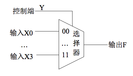
实验一 选择器 问题描述 用选择器模板实现一个2位4选1的选择器,如下图所示,选择器有5个2位输入端,分别为X0, X1, X2, X3和Y,输出端为F;X0, X1, X2, X3是四个2位的输入变量。输出F端受控制端Y的控制,选择其中的一个X输出,当Y = 00时,输出端输出X0,即F = X0;当Y = 01时,输出端输出X1,即F = X1;以此类推。
模板代码 1 2 3 4 5 6 7 8 9 10 11 12 13 14 15 16 17 18 19 20 21 22 23 24 25 26 27 28 29 30 31 32 33 34 35 36 37 38 39 40 41 42 43 44 45 46 47 48 49 50 51 52 module MuxKeyInternal #(NR_KEY = 2, KEY_LEN = 1, DATA_LEN = 1, HAS_DEFAULT = 0) ( output reg [DATA_LEN-1 :0 ] out, input [KEY_LEN-1 :0 ] key, input [DATA_LEN-1 :0 ] default_out, input [NR_KEY*(KEY_LEN + DATA_LEN)-1 :0 ] lut ); localparam PAIR_LEN = KEY_LEN + DATA_LEN; wire [PAIR_LEN-1 :0 ] pair_list [NR_KEY-1 :0 ]; wire [KEY_LEN-1 :0 ] key_list [NR_KEY-1 :0 ]; wire [DATA_LEN-1 :0 ] data_list [NR_KEY-1 :0 ]; generate for (genvar n = 0 ; n < NR_KEY; n = n + 1 ) begin assign pair_list[n] = lut[PAIR_LEN*(n+1 )-1 : PAIR_LEN*n]; assign data_list[n] = pair_list[n][DATA_LEN-1 :0 ]; assign key_list[n] = pair_list[n][PAIR_LEN-1 :DATA_LEN]; end endgenerate reg [DATA_LEN-1 : 0 ] lut_out; reg hit; integer i; always @(*) begin lut_out = 0 ; hit = 0 ; for (i = 0 ; i < NR_KEY; i = i + 1 ) begin lut_out = lut_out | ({DATA_LEN{key == key_list[i]}} & data_list[i]); hit = hit | (key == key_list[i]); end if (!HAS_DEFAULT) out = lut_out; else out = (hit ? lut_out : default_out); end endmodule module MuxKey #(NR_KEY = 2, KEY_LEN = 1, DATA_LEN = 1) ( output [DATA_LEN-1 :0 ] out, input [KEY_LEN-1 :0 ] key, input [NR_KEY*(KEY_LEN + DATA_LEN)-1 :0 ] lut ); MuxKeyInternal #(NR_KEY, KEY_LEN, DATA_LEN, 0) i0 (out, key, {DATA_LEN{1'b0}}, lut) ; endmodule module MuxKeyWithDefault #(NR_KEY = 2, KEY_LEN = 1, DATA_LEN = 1) ( output [DATA_LEN-1 :0 ] out, input [KEY_LEN-1 :0 ] key, input [DATA_LEN-1 :0 ] default_out, input [NR_KEY*(KEY_LEN + DATA_LEN)-1 :0 ] lut ); MuxKeyInternal #(NR_KEY, KEY_LEN, DATA_LEN, 1) i0 (out, key, default_out, lut) ; endmodule
具体实现 1 2 3 4 5 6 7 8 9 10 11 12 13 14 15 16 17 18 19 20 21 22 23 24 25 26 27 module mux4 ( input [1 :0 ] X0, input [1 :0 ] X1, input [1 :0 ] X2, input [1 :0 ] X3, input [1 :0 ] Y, output [1 :0 ] F ); assign F = Y[1 ] ? (Y[0 ] ? X3 : X2) : (Y[0 ] ? X1 : X0 ); endmodule module mux4 ( input [1 :0 ] X0, input [1 :0 ] X1, input [1 :0 ] X2, input [1 :0 ] X3, input [1 :0 ] Y, output [1 :0 ] F ); MuxKey #(NR_KEY = 4, KEY_LEN = 2, DATA_LEN = 2) inst_0 (F, Y, { 2'b00 , X0, 2'b01 , X1, 2'b10 , X2, 2'b11 , X3 }); endmodule
遇到的一些问题
verilator仿真的时候如何对多个v文件进行仿真(多个文件有层级关系,包括一个顶层文件):
尝试解决:
硬写,沿着报错解决:
出现报错:vsrc/top.v:9:5: This may be because there's no search path specified with -I<dir>.
添加-I路径:
verilator --cc --exe --trace --build -j -Wall csrc/main.cpp vsrc/top.v -I ./vsrc
无法解决问题。
正解 :指定顶层模块名字
verilator --cc --exe --trace --build -j -Wall csrc/main.cpp vsrc/* --top-module top
尝试使用参数化,格式错误;
正确格式为:
1
2
3
4
5
6
MuxKey #(.NR_KEY(4), .KEY_LEN(2), .DATA_LEN(2)) inst_0 (F, Y, { 2'b00 , X0, 2'b01 , X1, 2'b10 , X2, 2'b11 , X3 });
git merge 发生冲突如何解决
解决冲突 - 廖雪峰的官方网站
拓展:使用Chisel实现 1 2 3 4 5 6 7 8 9 10 11 12 13 14 15 16 17 18 19 20 21 22 23 24 25 class Mux4 extends Module val io = IO (new Bundle { val X0 = Input (UInt (2. W )) val X1 = Input (UInt (2. W )) val X2 = Input (UInt (2. W )) val X3 = Input (UInt (2. W )) val Y = Input (UInt (2. W )) val F = Output (UInt (2. W )) }) io.F := 0. U switch (io.Y ) { is(0. U ) { io.F := io.X0 } is(1. U ) { io.F := io.X1 } is(2. U ) { io.F := io.X2 } is(3. U ) { io.F := io.X3 } } }
实验二 译码器和编码器 问题描述 功能描述
查找8-3优先编码器相关原理和实现方法,实现一个8-3编码器,完成8-3编码器的设计、功能仿真和硬件实现。
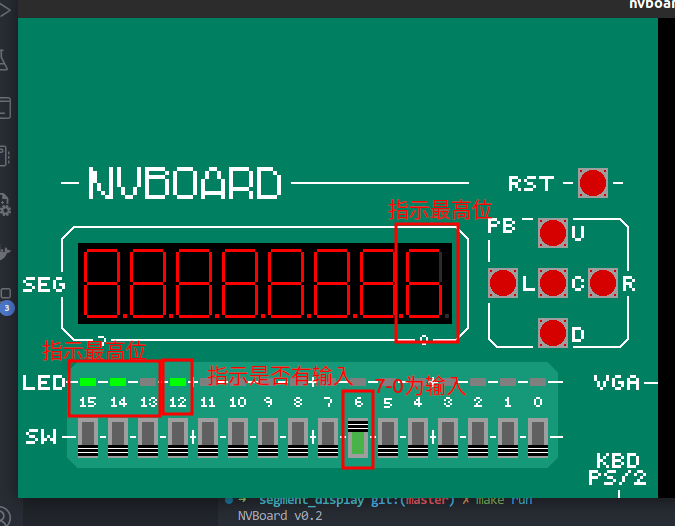
输入一个8位二进制数,对此8位二进制数进行高位优先编码成一个3位二进制值,并根据是否有输入增加一位输入指示位,即8个输入全0时指示位为0,有任何一个输入为1时指示位为1。编码器的使能端可选实现。将此编码结果及指示位以二进制形式显示在四个发光二极管LED上。再将此结果跟据七段数码管的显示进行译码,将二进制的优先编码结果以十进制的形式显示在数码管上。
输入输出建议
输入可以使用拨动开关SW7-SW0。使能端可以用SW8。输出为LED2-0,输出指示可以是LED4,数码管输出为HEX0。
例:我们从SW7—SW0输入00001110,因为我们设计的是一个高位优先的优先编码器,从左(高位)开始,第一位为1的是第3号位,那么优先编码器的编码二进制结果就为011,将这个值显示在发光二极管上,并且指示位也同时置为1。再对这个数值跟据七段数码管的显示进行译码,此时应显示为 3 ,用HEX0显示,所以HEX0[6:0]应该译码为0110000(注意高低位顺序),那么在七段数码管上就会显示 3 这个字符。
模块定义 1 2 3 4 5 6 module top ( input [7 :0 ] bin_i, output [2 :0 ] led_o, output [7 :0 ] seg_o ); endmodule
实现思路 编码器的实现可以使用case语句,并结合使用x、z(对输入的某些位进行无关项处理)。
具体实现 1 2 3 4 5 6 7 8 9 10 11 12 13 14 15 16 17 18 19 20 21 22 23 24 25 26 27 28 29 30 31 32 33 34 35 36 37 38 39 40 module coder( input [7 :0 ] bin_i, output reg in_flag, output [2 :0 ] led_o, output reg [7 :0 ] seg_o ); reg [2 :0 ] led;always @(*) begin in_flag = 1'b1 ; led = 3'b0 ; casez (bin_i) 8'b1zzzzzzz : led = 3'd7 ; 8'b01zzzzzz : led = 3'd6 ; 8'b001zzzzz : led = 3'd5 ; 8'b0001zzzz : led = 3'd4 ; 8'b00001zzz : led = 3'd3 ; 8'b000001zz : led = 3'd2 ; 8'b0000001z : led = 3'd1 ; 8'b00000001 : led = 3'd0 ; 8'b00000000 : in_flag = 1'b0 ; default : begin led = 3'b0 ; in_flag = 1'b1 ; end endcase end assign led_o = led;always @(*) begin case (led) 3'd0 : seg_o = 8'hC0 ; 3'd1 : seg_o = 8'hF9 ; 3'd2 : seg_o = 8'hA4 ; 3'd3 : seg_o = 8'hB0 ; 3'd4 : seg_o = 8'h99 ; 3'd5 : seg_o = 8'h92 ; 3'd6 : seg_o = 8'h82 ; 3'd7 : seg_o = 8'hF8 ; default : seg_o = 8'hC0 ; endcase end endmodule
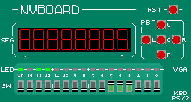
nvboard验证
拓展:使用chisel实现 遇到的问题:
直接使用PriorityEncoder生成的电路中,对于0输入的条件下,输出是全1,而不是全零,暂时没有找到问题所在。
实验三 加法器和ALU 加法器 问题描述 四位补码加减法器
模块定义 1 2 3 4 5 6 7 8 9 module adder ( input [3 :0 ] a_i, input [3 :0 ] b_i, output [3 :0 ] res_o, output c, output z, output o ); endmodule
实现思路 首先明确,这是补码,第一位是符号位;然后,把减法变换成加法(变补操作),然后利用verilog自带的(无符号数)加法器进行加法操作,得到结果信息并输出。
具体实现 1 2 3 4 5 6 7 8 9 10 11 12 13 14 15 16 17 18 19 20 21 22 23 module adder ( input [3 :0 ] a_i, input [3 :0 ] b_i, input addorsub_i, output [3 :0 ] res_o, output c, output z, output o ); reg [3 :0 ] s_b_i; always @(*) begin if (~addorsub_i) begin s_b_i = ~b_i + 1'b1 ; end else begin s_b_i = b_i; end end assign {c, res_o} = a_i + s_b_i; assign o = ~(a_i[3 ] ^ b_i[3 ]) & (a_i[3 ] ^ res_o[3 ]); assign z = ~ (| res_o); endmodule
ALU 问题描述 设计一个能实现如下功能的4位带符号位的 补码 ALU:
功能选择
功能
操作
000
加法
A+B
001
减法
A-B
010
取反
Not A
011
与
A and B
100
或
A or B
101
异或
A xor B
110
比较大小
If A<B then out=1; else out=0;
111
判断相等
If A==B then out=1; else out=0;
ALU进行加减运算时,需要能够判断结果是否为0,是否溢出,是否有进位等。这里,输入的操作数A和B都已经是补码。比较大小请按带符号数的方式设置。
执行逻辑操作时不需要考虑overflow和溢出。
由于开发板上输入有限,可以使用SW作为数据输入,button作为选择端。
模块定义 1 2 3 4 5 6 7 8 9 10 module alu( input [3 :0 ] a, input [3 :0 ] b, input [2 :0 ] op, output c, output reg z, output o, output reg [3 :0 ] res ); endmodule
实现思路 将加法器实例化到alu模块即可。
具体实现 1 2 3 4 5 6 7 8 9 10 11 12 13 14 15 16 17 18 19 20 21 22 23 24 25 26 27 28 29 30 31 32 33 34 35 36 37 38 39 40 41 42 43 44 45 46 47 48 49 50 51 52 53 54 55 56 57 58 59 60 module alu( input [3 :0 ] a, input [3 :0 ] b, input [2 :0 ] op, output c, output reg z, output o, output reg [3 :0 ] res ); wire addorsub = ((op == 3'b001 ) || (op == 3'b110 )) ? 1'b0 : 1'b1 ;wire [3 :0 ] adder_res;wire adder_z;adder adder_inst(.a_i (a), .b_i (b), .addorsub_i (addorsub), .res_o (adder_res), .c (c), .z (adder_z), .o (o)); always @(*) begin z = 0 ; case (op) 3'd0 : begin res = adder_res; z = adder_z; end 3'd1 : begin res = adder_res; z = adder_z; end 3'd2 : begin res = ~a; end 3'd3 : begin res = a & b; end 3'd4 : begin res = a | b; end 3'd5 : begin res = a ^ b; end 3'd6 : begin if (~a[3 ] && b[3 ]) res = 4'b0 ; else if (a[3 ] && ~b[3 ]) res = 4'b1 ; else if (adder_res[3 ]) res = 4'b1 ; else res = 4'b0 ; end 3'd7 : begin if (a == b) begin res = 4'b1 ; z = 1'b1 ; end else begin res = 4'b0 ; z = 1'b0 ; end end endcase end endmodule


