/** module top_module ( input sel, input [7:0] a, input [7:0] b, output out ); assign out = (~sel & a) | (sel & b); endmodule **/
module top_module ( input sel, input [7:0] a, input [7:0] b, output [7:0] out );
assign out = sel ? a : b;
endmodule
Referrence
1 2 3 4 5 6 7 8 9 10 11 12 13 14 15 16 17 18 19
module top_module ( input sel, input [7:0] a, input [7:0] b, outputreg [7:0] out );
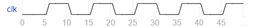
// 1. A mux coded as (~sel & a) | (sel & b) does not work for vectors. // This is because these are bitwise operators, and sel is only a 1 bit wide quantity, // which leaves the upper bits of a and b zeroed. It is possible to code it using // the replication operator, but this is somewhat difficult to read: // ( {8{~sel}} & a ) | ( {8{sel}} & b ) // 2. The simulation waveform shows that when sel = 1, a should be selected. This // is flipped in the suggested code.
assign out = sel ? a : b; endmodule
Bugs nand3
Question
This three-input NAND gate doesn’t work. Fix the bug(s).
You must use the provided 5-input AND gate:
module andgate ( output out, input a, input b, input c, input d, input e );
Module Declaration
1
module top_module (input a, input b, input c, output out);
always @(*) begin case (do_sub) 0: out = a+b; 1: out = a-b; endcase
if (!out) result_is_zero = 1; else result_is_zero = 0; end
endmodule
Bugs case
Question
This combinational circuit is supposed to recognize 8-bit keyboard scancodes for keys 0 through 9. It should indicate whether one of the 10 cases were recognized (valid), and if so, which key was detected. Fix the bug(s).
always @(*) case (code) 8'h45: out = 0; 8'h16: out = 1; 8'h1e: out = 2; 8'd26: out = 3; 8'h25: out = 4; 8'h2e: out = 5; 8'h36: out = 6; 8'h3d: out = 7; 8'h3e: out = 8; 6'h46: out = 9; default: valid = 0; endcase
endmodule
Bugs case
Quesiton
This combinational circuit is supposed to recognize 8-bit keyboard scancodes for keys 0 through 9. It should indicate whether one of the 10 cases were recognized (valid), and if so, which key was detected. Fix the bug(s).
// A combinational always block. always @(*) begin out = 0; // To avoid latches, give the outputs a default assignment valid = 1; // then override them in the case statement. This is less // code than assigning a value to every variable for every case. case (code) 8'h45: out = 0; 8'h16: out = 1; 8'h1e: out = 2; 8'h26: out = 3; // 8'd26 is 8'h1a 8'h25: out = 4; 8'h2e: out = 5; 8'h36: out = 6; 8'h3d: out = 7; 8'h3e: out = 8; 8'h46: out = 9; default: valid = 0; endcase end endmodule
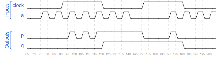
module top_module ( input clock, input a, output p, output q); always @(*) begin if (clock) p = a; else p = p; end always @(negedge clock) begin q <= a; end endmodule
Sim/circuit9
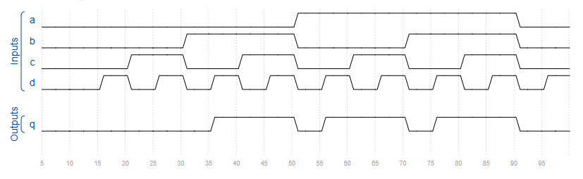
Question
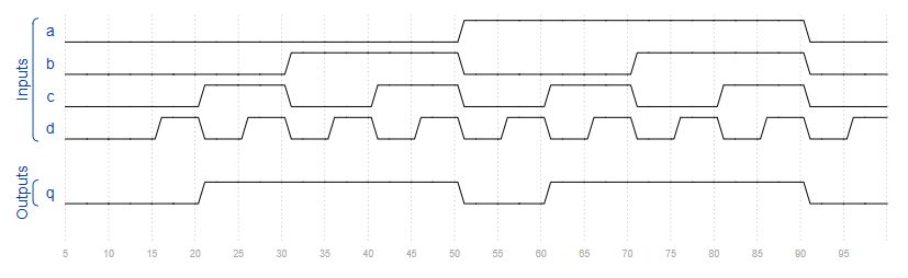
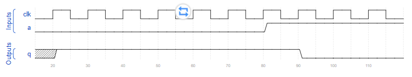
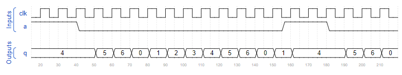
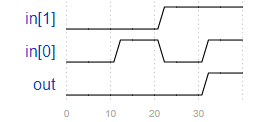
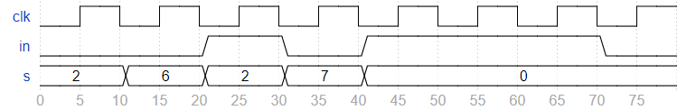
This is a sequential circuit. Read the simulation waveforms to determine what the circuit does, then implement it.
module top_module ( input clk, input a, output [3:0] q ); always @(posedge clk) begin if (a) q <= 4'd4; elsebegin if (q > 4'd5) q <= 0; else q <= q + 1'b1; end end endmodule
Sim/circuit10
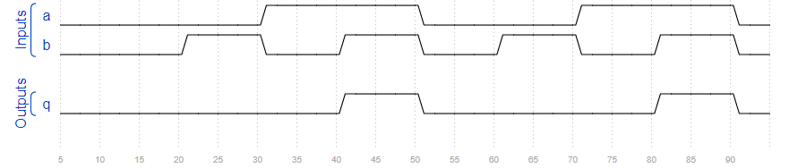
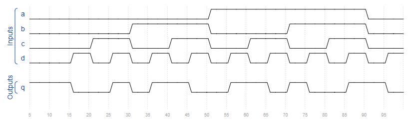
Question
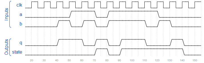
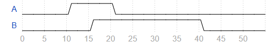
This is a sequential circuit. The circuit consists of combinational logic and one bit of memory (i.e., one flip-flop). The output of the flip-flop has been made observable through the output state.
Read the simulation waveforms to determine what the circuit does, then implement it.
Module Declaration
1
2
3
4
5
6
module top_module (
    input clk,
    input a,
    input b,
    output q,
    output state  );
module top_module (
    input clk,
    input a,
    input b,
    output q,
    output state  );
    reg next_state;

    always @(*)
        case (state)
            1'b0 : next_state = (a & b) ? 1'b1 : 1'b0;
            1'b1 : next_state = ~(a | b) ? 1'b0 : 1'b1; // 这里逻辑开始写错了,写成了~(a & b);
        endcase

    always @(posedge clk) begin
        state <= next_state;
    end

    assign q = state ? ~(a ^ b) : (a ^ b);
endmodule
Tb/clock
Question
You are provided a module with the following declaration:
module dut (input clk)
Write a testbench that creates one instance of module dut (with any instance name), and create a clock signal to drive the module’s clk input. The clock has a period of 10 ps. The clock should be initialized to zero with its first transition being 0 to 1.