module top_module( input clk, input areset, // Asynchronous reset to state B input in, output out);//
parameter A=1'b0, B=1'b1; reg state, next_state;
always @(*) begin// This is a combinational always block // State transition logic case (state) A: next_state = in ? A : B; B: next_state = in ? B : A; endcase end
always @(posedge clk, posedge areset) begin// This is a sequential always block // State flip-flops with asynchronous reset if (areset) state <= B; else state <= next_state; end
// Output logic assign out = state ? 1'b1 : 1'b0;
endmodule
Fsm1s
question
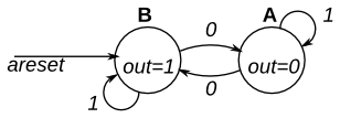
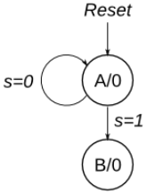
This is a Moore state machine with two states, one input, and one output. Implement this state machine. Notice that the reset state is B.
This exercise is the same as fsm1, but using synchronous reset.
这道题有点怪,为什么答案是用阻塞赋值
Module Declaration
1 2 3 4 5 6
// Note the Verilog-1995 module declaration syntax here: module top_module(clk, reset, in, out); input clk; input reset; // Synchronous reset to state B input in; output out;
// Note the Verilog-1995 module declaration syntax here: module top_module(clk, reset, in, out); input clk; input reset; // Synchronous reset to state B input in; output out;// reg out;
// Fill in state name declarations parameter A = 1'b0, B = 1'b1; reg present_state, next_state;
always @(posedge clk) begin if (reset) begin // Fill in reset logic present_state = B; out = 1'b1; endelsebegin case (present_state) // Fill in state transition logic A : next_state = in ? A : B; B : next_state = in ? B : A; endcase
// State flip-flops present_state = next_state;
case (present_state) // Fill in output logic A : out = 1'b0; B : out = 1'b1; endcase end end
endmodule
Fsm2
question
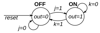
This is a Moore state machine with two states, two inputs, and one output. Implement this state machine.
This exercise is the same as fsm2s, but using asynchronous reset.
Module Declaration
1
2
3
4
5
6
module top_module( input clk, input areset, // Asynchronous reset to OFF input j, input k, output out);
module top_module( input clk, input areset, // Asynchronous reset to OFF input j, input k, output out); //
parameter OFF=0, ON=1; reg state, next_state;
always @(*) begin // State transition logic case (state) OFF : next_state = j ? ON : OFF; ON : next_state = k ? OFF : ON; endcase end
always @(posedge clk, posedge areset) begin // State flip-flops with asynchronous reset if (areset) state <= OFF; elsebegin state <= next_state; end end
// Output logic assign out = (state == ON);
endmodule
Fsm2s
question
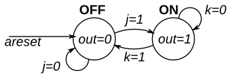
This is a Moore state machine with two states, two inputs, and one output. Implement this state machine.
This exercise is the same as fsm2, but using synchronous reset.
Module Declaration
1
2
3
4
5
6
module top_module( input clk, input reset, // Synchronous reset to OFF input j, input k, output out);
module top_module( input clk, input areset, // Asynchronous reset to OFF input j, input k, output out); //
parameter OFF=0, ON=1; reg state, next_state;
always @(*) begin // State transition logic case (state) OFF : next_state = j ? ON : OFF; ON : next_state = k ? OFF : ON; endcase end
always @(posedge clk) begin // State flip-flops with asynchronous reset if (areset) state <= OFF; elsebegin state <= next_state; end end
// Output logic assign out = (state == ON);
endmodule
Fsm3comb
question
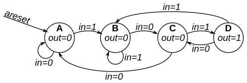
The following is the state transition table for a Moore state machine with one input, one output, and four states. Use the following state encoding: A=2’b00, B=2’b01, C=2’b10, D=2’b11.
Implement only the state transition logic and output logic (the combinational logic portion) for this state machine. Given the current state (state), compute the next_state and output (out) based on the state transition table.
// State transition logic: next_state = f(state, in) always @(*) begin case (state) A: next_state = in ? B : A; B: next_state = in ? B : C; C: next_state = in ? D : A; D: next_state = in ? B : C; endcase end // Output logic: out = f(state) for a Moore state machine assign out = (state == D); endmodule
Fsm3onehot
question
The following is the state transition table for a Moore state machine with one input, one output, and four states. Use the following one-hot state encoding: A=4’b0001, B=4’b0010, C=4’b0100, D=4’b1000.
Derive state transition and output logic equations by inspection assuming a one-hot encoding. Implement only the state transition logic and output logic (the combinational logic portion) for this state machine. (The testbench will test with non-one hot inputs to make sure you’re not trying to do something more complicated).
State
Next state
Next state
Output
in=0
in=1
A
A
B
0
B
C
B
0
C
A
D
0
D
C
B
1
What does “derive equations by inspection” mean?
One-hot state machine encoding guarantees that exactly one state bit is 1. This means that it is possible to determine whether the state machine is in a particular state by examining only one state bit, not all state bits. This leads to simple logic equations for the state transitions by examining the incoming edges for each state in the state transition diagram.
For example, in the above state machine, how can the state machine can reach state A? It must use one of the two incoming edges: “Currently in state A and in=0” or “Currently in state C and in = 0”. Due to the one-hot encoding, the logic equation to test for “currently in state A” is simply the state bit for state A. This leads to the final logic equation for the next state of state bit A: next_state[0] = state[0]&(~in) | state[2]&(~in). The one-hot encoding guarantees that at most one clause (product term) will be “active” at a time, so the clauses can just be ORed together.
When an exercise asks for state transition equations “by inspection”, use this particular method. The judge will test with non-one-hot inputs to ensure your logic equations follow this method, rather that doing something else (such as resetting the FSM) for illegal (non-one-hot) combinations of the state bits.
Although knowing this algorithm isn’t necessary for RTL-level design (the logic synthesizer handles this), it is illustrative of why one-hot FSMs often have simpler logic (at the expense of more state bit storage), and this topic frequently shows up on exams in digital logic courses.
The following is the state transition table for a Moore state machine with one input, one output, and four states. Implement this state machine. Include an asynchronous reset that resets the FSM to state A.
State
Next state
Next state
Output
in=0
in=1
A
A
B
0
B
C
B
0
C
A
D
0
D
C
B
1
Module Declaration
1 2 3 4 5
module top_module( input clk, input in, input areset, output out);
// State transition logic parameter A=0, B=1, C=2, D=3;
// State transition logic: next_state = f(state, in) always @(*) begin case (state) A: next_state = in ? B : A; B: next_state = in ? B : C; C: next_state = in ? D : A; D: next_state = in ? B : C; endcase end // State flip-flops with asynchronous reset always @(posedge clk orposedge areset) begin if (areset) state <= A; else state <= next_state; end // Output logic: out = f(state) for a Moore state machine assign out = (state == D); endmodule
/* reference */ /* module top_module ( input clk, input in, input areset, output out ); // Give state names and assignments. I'm lazy, so I like to use decimal numbers. // It doesn't really matter what assignment is used, as long as they're unique. parameter A=0, B=1, C=2, D=3; reg [1:0] state; // Make sure state and next are big enough to hold the state encodings. reg [1:0] next; // Combinational always block for state transition logic. Given the current state and inputs, // what should be next state be? // Combinational always block: Use blocking assignments. always@(*) begin case (state) A: next = in ? B : A; B: next = in ? B : C; C: next = in ? D : A; D: next = in ? B : C; endcase end // Edge-triggered always block (DFFs) for state flip-flops. Asynchronous reset. always @(posedge clk, posedge areset) begin if (areset) state <= A; else state <= next; end // Combinational output logic. In this problem, an assign statement is the simplest. assign out = (state==D); endmodule */
The following is the state transition table for a Moore state machine with one input, one output, and four states. Implement this state machine. Include a synchronous reset that resets the FSM to state A. (This is the same problem as Fsm3 but with a synchronous reset.)
State
Next state
Next state
Output
in=0
in=1
A
A
B
0
B
C
B
0
C
A
D
0
D
C
B
1
Module Declaration
1 2 3 4 5
module top_module( input clk, input in, input reset, output out);
// State transition logic parameter A = 2'b00, B = 2'b01, C = 2'b10, D = 2'b11; reg [1:0] state, next_state; always @(*) begin case (state) A : next_state = in ? B : A; B : next_state = in ? B : C; C : next_state = in ? D : A; D : next_state = in ? B : C; endcase end // State flip-flops with synchronous reset always @(posedge clk) begin if (reset) begin state <= A; end elsebegin state <= next_state; end end // Output logic always @(*) begin case (state) A : out = 0; B : out = 0; C : out = 0; D : out = 1'b1; endcase end endmodule
debug
开始设置state、next_state的位宽出现了问题:忘记写[1:0]。
Exams/ece241 2013 q4
question
Also include an active-high synchronous reset that resets the state machine to a state equivalent to if the water level had been low for a long time (no sensors asserted, and all four outputs asserted).
// Give state names and assignments. I'm lazy, so I like to use decimal numbers. // It doesn't really matter what assignment is used, as long as they're unique. // We have 6 states here. parameter A2=0, B1=1, B2=2, C1=3, C2=4, D1=5; reg [2:0] state, next; // Make sure these are big enough to hold the state encodings.
// Edge-triggered always block (DFFs) for state flip-flops. Synchronous reset. always @(posedge clk) begin if (reset) state <= A2; else state <= next; end
// Combinational always block for state transition logic. Given the current state and inputs, // what should be next state be? // Combinational always block: Use blocking assignments. always@(*) begin case (state) A2: next = s[1] ? B1 : A2; B1: next = s[2] ? C1 : (s[1] ? B1 : A2); B2: next = s[2] ? C1 : (s[1] ? B2 : A2); C1: next = s[3] ? D1 : (s[2] ? C1 : B2); C2: next = s[3] ? D1 : (s[2] ? C2 : B2); D1: next = s[3] ? D1 : C2; default: next = 'x; endcase end
// Combinational output logic. In this problem, a procedural block (combinational always block) // is more convenient. Be careful not to create a latch. always@(*) begin case (state) A2: {fr3, fr2, fr1, dfr} = 4'b1111; B1: {fr3, fr2, fr1, dfr} = 4'b0110; B2: {fr3, fr2, fr1, dfr} = 4'b0111; C1: {fr3, fr2, fr1, dfr} = 4'b0010; C2: {fr3, fr2, fr1, dfr} = 4'b0011; D1: {fr3, fr2, fr1, dfr} = 4'b0000; default: {fr3, fr2, fr1, dfr} = 'x; endcase end
The game Lemmings involves critters with fairly simple brains. So simple that we are going to model it using a finite state machine.
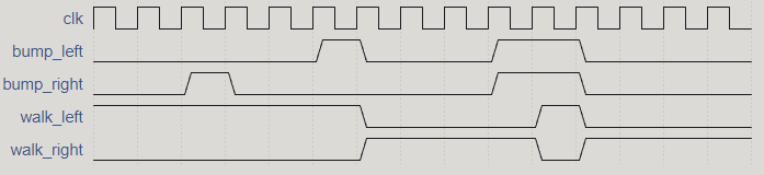
In the Lemmings’ 2D world, Lemmings can be in one of two states: walking left or walking right. It will switch directions if it hits an obstacle. In particular, if a Lemming is bumped on the left, it will walk right. If it’s bumped on the right, it will walk left. If it’s bumped on both sides at the same time, it will still switch directions.
Implement a Moore state machine with two states, two inputs, and one output that models this behaviour.
always @(*) begin // State transition logic case (state) LEFT : next_state = (bump_left) ? RIGHT : LEFT; RIGHT : next_state = (bump_right) ? LEFT : RIGHT; default : next_state = LEFT; endcase end
always @(posedge clk, posedge areset) begin // State flip-flops with asynchronous reset if (areset == 1'b1) begin state <= LEFT; end elsebegin state <= next_state; end end
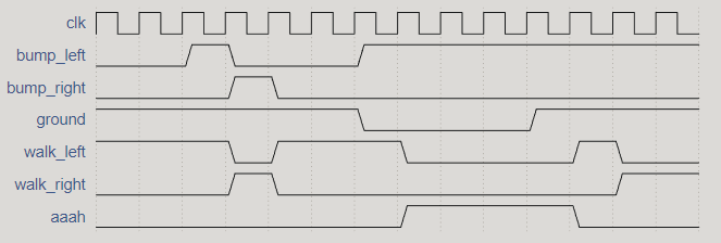
In addition to walking left and right, Lemmings will fall (and presumably go “aaah!”) if the ground disappears underneath them.
In addition to walking left and right and changing direction when bumped, when ground=0, the Lemming will fall and say “aaah!”. When the ground reappears (ground=1), the Lemming will resume walking in the same direction as before the fall. Being bumped while falling does not affect the walking direction, and being bumped in the same cycle as ground disappears (but not yet falling), or when the ground reappears while still falling, also does not affect the walking direction.
Build a finite state machine that models this behaviour.
parameter LEFT = 2'b00, LEFT_FALL = 2'b01, RIGHT = 2'b10, RIGHT_FALL = 2'b11;
reg [1:0] state, next_state; // state transition always @(*) begin // State transition logic case (state) LEFT : next_state = (!ground) ? LEFT_FALL : (bump_left ? RIGHT : LEFT); RIGHT : next_state = (!ground) ? RIGHT_FALL : (bump_right ? LEFT : RIGHT); LEFT_FALL : next_state = ground ? LEFT : LEFT_FALL; RIGHT_FALL : next_state = ground ? RIGHT : RIGHT_FALL; default : next_state = LEFT; endcase end
always @(posedge clk, posedge areset) begin // State flip-flops with asynchronous reset if (areset == 1'b1) begin state <= LEFT; end elsebegin state <= next_state; end end
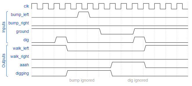
In addition to walking and falling, Lemmings can sometimes be told to do useful things, like dig (it starts digging when dig=1). A Lemming can dig if it is currently walking on ground (ground=1 and not falling), and will continue digging until it reaches the other side (ground=0). At that point, since there is no ground, it will fall (aaah!), then continue walking in its original direction once it hits ground again. As with falling, being bumped while digging has no effect, and being told to dig when falling or when there is no ground is ignored.
(In other words, a walking Lemming can fall, dig, or switch directions. If more than one of these conditions are satisfied, fall has higher precedence than dig, which has higher precedence than switching directions.)
Extend your finite state machine to model this behaviour.
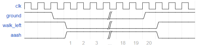
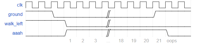
Although Lemmings can walk, fall, and dig, Lemmings aren’t invulnerable. If a Lemming falls for too long then hits the ground, it can splatter. In particular, if a Lemming falls for more than 20 clock cycles then hits the ground, it will splatter and cease walking, falling, or digging (all 4 outputs become 0), forever (Or until the FSM gets reset). There is no upper limit on how far a Lemming can fall before hitting the ground. Lemmings only splatter when hitting the ground; they do not splatter in mid-air.
Extend your finite state machine to model this behaviour.
// counter always @(posedge clk orposedge areset) begin if (areset) begin cnt <= 0; end elsebegin if ((state == FL) || (state == FR)) begin cnt <= cnt + 1'b1; end else cnt <= 0; end end
// splat always @(*) begin if (areset) begin splat = 0; end elsebegin if (cnt == 6'd20) begin splat = 1'b1; end elsebegin splat = splat; end end end
Given the following state machine with 1 input and 2 outputs:
Suppose this state machine uses one-hot encoding, where state[0] through state[9] correspond to the states S0 though S9, respectively. The outputs are zero unless otherwise specified.
Implement the state transition logic and output logic portions of the state machine (but not the state flip-flops). You are given the current state in state[9:0] and must produce next_state[9:0] and the two outputs. Derive the logic equations by inspection assuming a one-hot encoding. (The testbench will test with non-one hot inputs to make sure you’re not trying to do something more complicated).
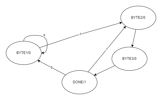
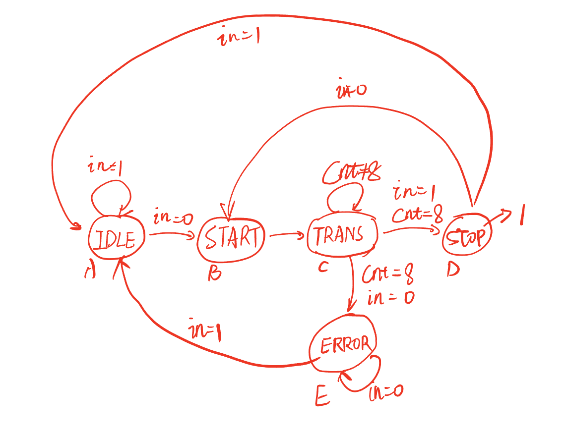
The PS/2 mouse protocol sends messages that are three bytes long. However, within a continuous byte stream, it’s not obvious where messages start and end. The only indication is that the first byte of each three byte message always has bit[3]=1 (but bit[3] of the other two bytes may be 1 or 0 depending on data).
We want a finite state machine that will search for message boundaries when given an input byte stream. The algorithm we’ll use is to discard bytes until we see one with bit[3]=1. We then assume that this is byte 1 of a message, and signal the receipt of a message once all 3 bytes have been received (done).
The FSM should signal done in the cycle immediately after the third byte of each message was successfully received.
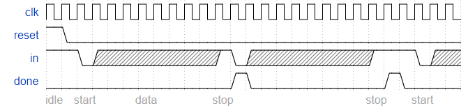
Some timing diagrams to explain the desired behaviour
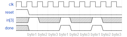
Under error-free conditions, every three bytes form a message:
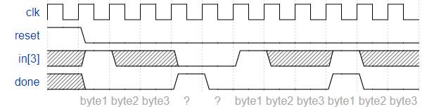
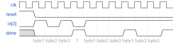
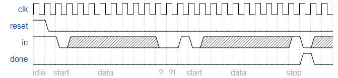
When an error occurs, search for byte 1:
Note that this is not the same as a 1xx sequence recognizer. Overlapping sequences are not allowed here:
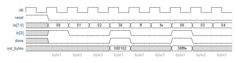
Now that you have a state machine that will identify three-byte messages in a PS/2 byte stream, add a datapath that will also output the 24-bit (3 byte) message whenever a packet is received (out_bytes[23:16] is the first byte, out_bytes[15:8] is the second byte, etc.).
out_bytes needs to be valid whenever the done signal is asserted. You may output anything at other times (i.e., don’t-care).
module top_module( input clk, input [7:0] in, input reset, // Synchronous reset output [23:0] out_bytes, output done); localparam BYTE1 = 2'b00, BYTE2 = 2'b01, BYTE3 = 2'b10, DONE = 2'b11; reg [1:0] current_state, next_state; // State transition logic (combinational) always @(*) begin case (current_state) BYTE1 : next_state = in[3] ? BYTE2 : BYTE1; BYTE2 : next_state = BYTE3; BYTE3 : next_state = DONE; DONE : next_state = in[3] ? BYTE2 : BYTE1; endcase end // State flip-flops (sequential) always @(posedge clk) begin if (reset) begin current_state <= BYTE1; end else current_state <= next_state; end // Output logic assign done = (current_state == DONE) ? 1'b1 : 1'b0; // Datapath to store incoming bytes always @(posedge clk) begin if (current_state == BYTE2) out_bytes[15:8] <= in; elseif (current_state == BYTE3) out_bytes[7:0] <= in; else out_bytes[23:16] <= in; end endmodule
Debug
最开始的数据通路写错了,没有考虑到Done有时候是对应于第一个字节:
1
2
3
4
5
6
// Datapath to store incoming bytes always @(posedge clk) begin if (current_state == BYTE1) out_bytes[23:16] <= in; elseif (current_state == BYTE2) out_bytes[15:8] <= in; elseif (current_state == BYTE3) out_bytes[7:0] <= in; end
改过之后:
1
2
3
4
5
6
// Datapath to store incoming bytes always @(posedge clk) begin if (current_state == BYTE2) out_bytes[15:8] <= in; elseif (current_state == BYTE3) out_bytes[7:0] <= in; else out_bytes[23:16] <= in; end
Fsm serial
question
In many (older) serial communications protocols, each data byte is sent along with a start bit and a stop bit, to help the receiver delimit bytes from the stream of bits. One common scheme is to use one start bit (0), 8 data bits, and 1 stop bit (1). The line is also at logic 1 when nothing is being transmitted (idle).
Design a finite state machine that will identify when bytes have been correctly received when given a stream of bits. It needs to identify the start bit, wait for all 8 data bits, then verify that the stop bit was correct. If the stop bit does not appear when expected, the FSM must wait until it finds a stop bit before attempting to receive the next byte.
Now that you have a finite state machine that can identify when bytes are correctly received in a serial bitstream, add a datapath that will output the correctly-received data byte. out_byte needs to be valid when done is 1, and is don’t-care otherwise.
Note that the serial protocol sends the least significant bit first
// datapath always @(posedge clk) begin if (next_state == TRANS) begin integer i; out_byte[7] <= in; for (i = 0; i <= 6; i = i + 1) begin : datapath_loop out_byte[i] <= out_byte[i + 1]; end end end endmodule
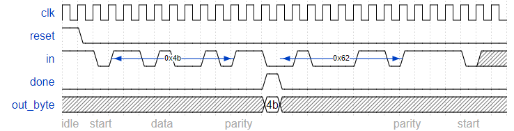
We want to add parity checking to the serial receiver. Parity checking adds one extra bit after each data byte. We will use odd parity, where the number of 1s in the 9 bits received must be odd. For example, 101001011 satisfies odd parity (there are 5 1s), but 001001011 does not.
Change your FSM and datapath to perform odd parity checking. Assert the done signal only if a byte is correctly received and its parity check passes. Like the serial receiver FSM, this FSM needs to identify the start bit, wait for all 9 (data and parity) bits, then verify that the stop bit was correct. If the stop bit does not appear when expected, the FSM must wait until it finds a stop bit before attempting to receive the next byte.
You are provided with the following module that can be used to calculate the parity of the input stream (It’s a TFF with reset). The intended use is that it should be given the input bit stream, and reset at appropriate times so it counts the number of 1 bits in each byte.
1 2 3 4 5 6 7 8 9 10 11 12 13
module parity ( input clk, input reset, input in, outputreg odd); always @(posedge clk) if (reset) odd <= 0; elseif (in) odd <= ~odd; endmodule Note that the serial protocol sends the least significant bit first, and the parity bit after the 8 data bits.
Some timing diagrams
No framing errors. Odd parity passes for first byte, fails for second byte.
// datapath always @(posedge clk) begin if (next_state == TRANS) begin integer i; out_byte[7] <= in; for (i = 0; i <= 6; i = i + 1) begin : datapath_loop out_byte[i] <= out_byte[i + 1]; end end end
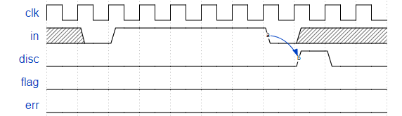
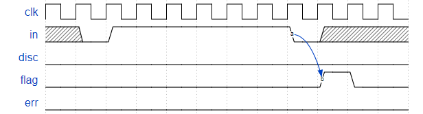
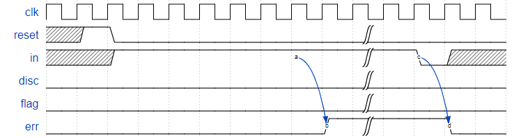
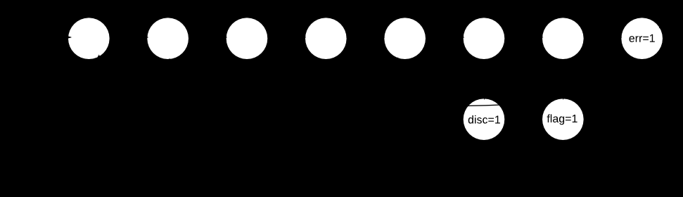
Synchronous HDLC framing involves decoding a continuous bit stream of data to look for bit patterns that indicate the beginning and end of frames (packets). Seeing exactly 6 consecutive 1s (i.e., 01111110) is a “flag” that indicate frame boundaries. To avoid the data stream from accidentally containing “flags”, the sender inserts a zero after every 5 consecutive 1s which the receiver must detect and discard. We also need to signal an error if there are 7 or more consecutive 1s.
Create a finite state machine to recognize these three sequences:
0111110: Signal a bit needs to be discarded (disc).
01111110: Flag the beginning/end of a frame (flag).
01111111…: Error (7 or more 1s) (err).
When the FSM is reset, it should be in a state that behaves as though the previous input were 0.
Here are some example sequences that illustrate the desired operation.
module top_module( input clk, input reset, // Synchronous reset input in, output disc, output flag, output err); reg [9:0] next_state, state; always @(*) begin next_state[0] = (~in & (state[0] | state[1] | state[2] | state[3] | state[4] | state[7] | state[8] | state[9])); next_state[1] = (in & (state[0] | state[8] | state[9])); next_state[2] = (in & state[1]); next_state[3] = (in & state[2]); next_state[4] = (in & state[3]); next_state[5] = (in & state[4]); next_state[6] = (in & state[5]); next_state[7] = (in & (state[7] | state[6])); next_state[8] = (~in & state[5]); next_state[9] = (~in & state[6]); end always @(posedge clk) begin if (reset) state <= 10'b1; // 注意:这里复位不是0,要根据独热码的规则。 else state <= next_state; end assign err = state[7]; assign disc = state[8]; assign flag = state[9]; endmodule
Debug
注意:复位状态时10’b1,这里用了上面独热码题目(onehot)的代码。
Exams/ece241 2013 q8
Question
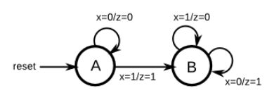
Implement a Mealy-type finite state machine that recognizes the sequence “101” on an input signal named x. Your FSM should have an output signal, z, that is asserted to logic-1 when the “101” sequence is detected. Your FSM should also have an active-low asynchronous reset. You may only have 3 states in your state machine. Your FSM should recognize overlapping sequences.
// Give state names and assignments. I'm lazy, so I like to use decimal numbers. // It doesn't really matter what assignment is used, as long as they're unique. parameter S=0, S1=1, S10=2; reg[1:0] state, next; // Make sure state and next are big enough to hold the state encodings. // Edge-triggered always block (DFFs) for state flip-flops. Asynchronous reset. always@(posedge clk, negedge aresetn) if (!aresetn) state <= S; else state <= next;
// Combinational always block for state transition logic. Given the current state and inputs, // what should be next state be? // Combinational always block: Use blocking assignments. always@(*) begin case (state) S: next = x ? S1 : S; S1: next = x ? S1 : S10; S10: next = x ? S1 : S; default: next = 'x; endcase end // Combinational output logic. I used a combinational always block. // In a Mealy state machine, the output depends on the current state *and* // the inputs. always@(*) begin case (state) S: z = 0; S1: z = 0; S10: z = x; // This is a Mealy state machine: The output can depend (combinational) on the input. default: z = 1'bx; endcase end endmodule
Exams/ece241 2014 q5a
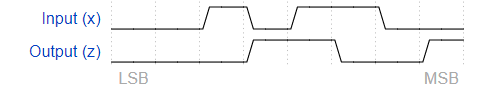
注意:这道题默认输入是负数并且省略了符号位。
Question
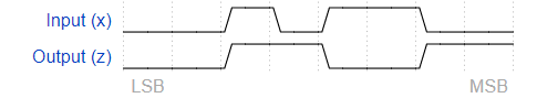
You are to design a one-input one-output serial 2’s complementer Moore state machine. The input (x) is a series of bits (one per clock cycle) beginning with the least-significant bit of the number, and the output (Z) is the 2’s complement of the input. The machine will accept input numbers of arbitrary length. The circuit requires an asynchronous reset. The conversion begins when Reset is released and stops when Reset is asserted.
always @(*) begin case (state) A : next_state = x ? B : A; B : next_state = B; endcase end
always @(posedge clk orposedge areset) begin if (areset) begin state <= A; end elsebegin state <= next_state; end end
assign z = ((state == A) & ( x == 1'b1)) | ((state == B) & (x == 0)); endmodule
Exams/2014 q3fsm
Question
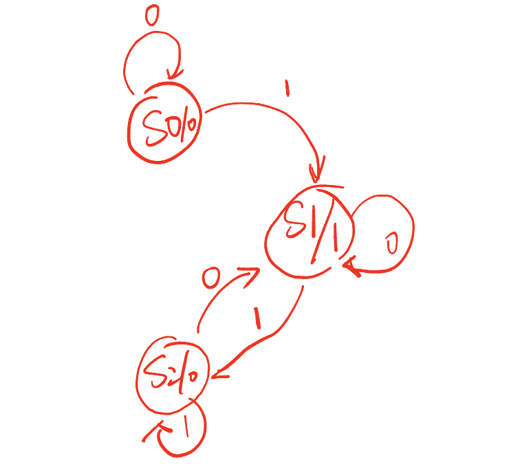
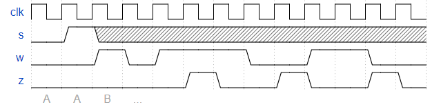
Consider a finite state machine with inputs s and w. Assume that the FSM begins in a reset state called A, as depicted below. The FSM remains in state A as long as s = 0, and it moves to state B when s = 1. Once in state B the FSM examines the value of the input w in the next three clock cycles. If w = 1 in exactly two of these clock cycles, then the FSM has to set an output z to 1 in the following clock cycle. Otherwise z has to be 0. The FSM continues checking w for the next three clock cycles, and so on. The timing diagram below illustrates the required values of z for different values of w.
Use as few states as possible. Note that the s input is used only in state A, so you need to consider just the w input.
always @(*) begin case (state) A : next_state = s ? B : A; B : next_state = B; default : next_state = B; endcase end
always @(posedge clk) begin if (reset) begin state <= A; end elsebegin state <= next_state; end end
always @(posedge clk) begin if (reset) begin cnt <= 0; end elsebegin if (state == B) begin if (cnt == 2'b10) cnt <= 0; else cnt <= cnt + 1'b1; end elsebegin cnt <= 0; end end end
always @(posedge clk) begin if (reset) begin flag <= 0; end elsebegin if (cnt == 2'b10) begin if ((f_cnt == 2'b01) && (w == 1'b1)) flag <= 1'b1; elseif ((f_cnt == 2'b10) && (w == 1'b0)) begin flag <= 1'b1; end elsebegin flag <= 1'b0; end end if (flag == 1'b1) flag <= 1'b0; end end
always @(posedge clk) begin if (reset) begin f_cnt <= 0; end elsebegin // 最开始这里没有判断在 state == B, 出现了bug if (state == B) begin if (cnt == 2'b10) f_cnt <= 0; elseif (w == 1'b1) f_cnt <= f_cnt + 1'b1; elsebegin f_cnt <= f_cnt; end end end end
assign z = flag; endmodule
Debug
见代码注释
Exams/2014 q3bfsm
Question
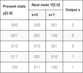
Given the state-assigned table shown below, implement the finite-state machine. Reset should reset the FSM to state 000.
module top_module ( input clk, input reset, // Synchronous reset input x, output z); localparam A = 0, B = 1, C = 2, D = 3, E = 4; reg [2:0] state, next_state;
always @(*) begin case (state) A : next_state = x ? B : A; B : next_state = x ? E : B; C : next_state = x ? B : C; D : next_state = x ? C : B; E : next_state = x ? E : D; endcase end
always @(posedge clk) begin if (reset) state <= A; elsebegin state <= next_state; end end
assign z = (state == D) | (state == E); endmodule
Exams/2014 q3c
Question
Given the state-assigned table shown below, implement the logic functions Y[0] and z.
Module Declaration
1 2 3 4 5 6 7
module top_module ( input clk, input [2:0] y, input x, output Y0, output z );
module top_module ( input clk, input [2:0] y, input x, output Y0, output z ); localparam A = 0, B = 1, C = 2, D = 3, E = 4; reg [2:0] next_state;
always @(*) begin case (y) A : next_state = x ? B : A; B : next_state = x ? E : B; C : next_state = x ? B : C; D : next_state = x ? C : B; E : next_state = x ? E : D; endcase end
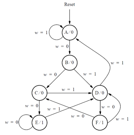
Consider the state machine shown below, which has one input w and one output z.
Assume that you wish to implement the FSM using three flip-flops and state codes y[3:1] = 000, 001, … , 101 for states A, B, … , F, respectively. Show a state-assigned table for this FSM. Derive a next-state expression for the flip-flop y[2].
Implement just the next-state logic for y[2]. (This is much more a FSM question than a Verilog coding question. Oh well.)
Module Declaration
1 2 3 4
module top_module ( input [3:1] y, input w, output Y2);
module top_module ( input [3:1] y, input w, output Y2);
localparam A = 0, B = 1, C = 2, D = 3, E = 4, F = 5; reg [3:1] next_state; always @(*) begin case (y) A : next_state = w ? A : B; B : next_state = w ? D : C; C : next_state = w ? D : E; D : next_state = w ? A : F; E : next_state = w ? D : E; F : next_state = w ? D : C; endcase end
assign Y2 = next_state[2]; endmodule
Tips
这道题理论上应该使用数电课上学的状态机到电路的实现方法来做,使用ffr的情况。
Exams/m2014 q6c
Question
Consider the state machine shown below, which has one input w and one output z.
For this part, assume that a one-hot code is used with the state assignment ‘y[6:1]_ = 000001, 000010, 000100, 001000, 010000, 100000 for states A, B,…, F, respectively._
Write a logic expression for the next-state signals Y2 and Y4. (Derive the logic equations by inspection assuming a one-hot encoding. The testbench will test with non-one hot inputs to make sure you’re not trying to do something more complicated).
localparam A = 0, B = 1, C = 2, D = 3, E = 4, F = 5; reg [3:1] state, next_state; always @(*) begin case (state) A : next_state = w ? A : B; B : next_state = w ? D : C; C : next_state = w ? D : E; D : next_state = w ? A : F; E : next_state = w ? D : E; F : next_state = w ? D : C; endcase end
always @(posedge clk) begin if (reset) state <= A; else state <= next_state; end assign z = (state == E) | (state == F); endmodule
Exams/2012 q2fsm
Question
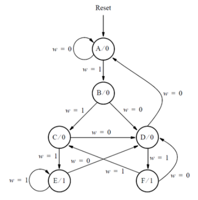
Consider the state diagram shown below.
Write complete Verilog code that represents this FSM. Use separate always blocks for the state table and the state flip-flops, as done in lectures. Describe the FSM output, which is called z, using either continuous assignment statement(s) or an always block (at your discretion). Assign any state codes that you wish to use.
localparam A = 0, B = 1, C = 2, D = 3, E = 4, F = 5; reg [3:1] state, next_state; wire r_w; assign r_w = ~w; always @(*) begin case (state) A : next_state = r_w ? A : B; B : next_state = r_w ? D : C; C : next_state = r_w ? D : E; D : next_state = r_w ? A : F; E : next_state = r_w ? D : E; F : next_state = r_w ? D : C; endcase end
always @(posedge clk) begin if (reset) state <= A; else state <= next_state; end assign z = (state == E) | (state == F); endmodule
Debug
注意状态机和上面几个不一样。
Exams/2012 q2b
Question
The state diagram for this question is shown again below.
Assume that a one-hot code is used with the state assignment y[5:0] = 000001(A), 000010(B), 000100(C), 001000(D), 010000(E), 100000(F)
Write a logic expression for the signal Y1, which is the input of state flip-flop y[1].
Write a logic expression for the signal Y3, which is the input of state flip-flop y[3].
(Derive the logic equations by inspection assuming a one-hot encoding. The testbench will test with non-one hot inputs to make sure you’re not trying to do something more complicated).
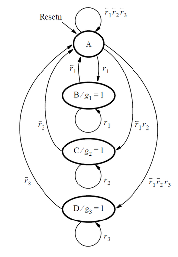
Consider the FSM described by the state diagram shown below:
This FSM acts as an arbiter circuit, which controls access to some type of resource by three requesting devices. Each device makes its request for the resource by setting a signal r[i] = 1, where r[i] is either r[1], r[2], or r[3]. Each r[i] is an input signal to the FSM, and represents one of the three devices. The FSM stays in state A as long as there are no requests. When one or more request occurs, then the FSM decides which device receives a grant to use the resource and changes to a state that sets that device’s g[i] signal to 1. Each g[i] is an output from the FSM. There is a priority system, in that device 1 has a higher priority than device 2, and device 3 has the lowest priority. Hence, for example, device 3 will only receive a grant if it is the only device making a request when the FSM is in state A. Once a device, i, is given a grant by the FSM, that device continues to receive the grant as long as its request, r[i] = 1.
Write complete Verilog code that represents this FSM. Use separate always blocks for the state table and the state flip-flops, as done in lectures. Describe the FSM outputs, g[i], using either continuous assignment statement(s) or an always block (at your discretion). Assign any state codes that you wish to use.
module top_module ( input clk, input resetn, // active-low synchronous reset input [3:1] r, // request output [3:1] g // grant ); localparam A = 2'b00, B = 2'b01, C = 2'b10, D = 2'b11; reg [1:0] state, next_state;
always @(*) begin case (state) A : next_state = r[1] ? B : r[2] ? C : r[3] ? D : A; B : next_state = r[1] ? B : A; C : next_state = r[2] ? C : A; D : next_state = r[3] ? D : A; endcase end
always @(posedge clk) begin if (~resetn) begin state <= A; end elsebegin state <= next_state; end end
Consider a finite state machine that is used to control some type of motor. The FSM has inputs x and y, which come from the motor, and produces outputs f and g, which control the motor. There is also a clock input called clk and a reset input called resetn.
The FSM has to work as follows. As long as the reset input is asserted, the FSM stays in a beginning state, called state A. When the reset signal is de-asserted, then after the next clock edge the FSM has to set the output f to 1 for one clock cycle. Then, the FSM has to monitor the x input. When x has produced the values 1, 0, 1 in three successive clock cycles, then g should be set to 1 on the following clock cycle. While maintaining g = 1 the FSM has to monitor the y input. If y has the value 1 within at most two clock cycles, then the FSM should maintain g = 1 permanently (that is, until reset). But if y does not become 1 within two clock cycles, then the FSM should set g = 0 permanently (until reset).
(The original exam question asked for a state diagram only. But here, implement the FSM.)
Module Declaration
1 2 3 4 5 6 7 8
module top_module (
    input clk,
    input resetn,    // active-low synchronous reset
    input x,
    input y,
    output f,
    output g
);
module top_module ( input clk, input resetn, // active-low synchronous reset input x, input y, output f, output g ); localparam A = 0, B = 1, C = 2, D = 3, E = 4, F = 5, G = 6, H = 7, I = 8; reg [3:0] state, next_state;
always @(*) begin case (state) A : next_state = B; B : next_state = C; C : next_state = x ? D : C; D : next_state = x ? D : E; E : next_state = x ? F : C; F : next_state = y ? I : G; G : next_state = y ? I : H; H : next_state = H; I : next_state = I; default : next_state = A; endcase end
always @(posedge clk) begin if (~resetn) state <= A; elsebegin state <= next_state; end end
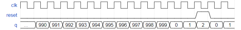
module top_module ( input clk, input reset, output [9:0] q); always @(posedge clk) begin if (reset) begin q <= 0; end elsebegin if (q > 10'd998) q <= 0; else q <= q + 1'b1; end end endmodule
Exams/review2015 shiftcount
Question
This is the first component in a series of five exercises that builds a complex counter out of several smaller circuits. See the final exercise for the overall design.
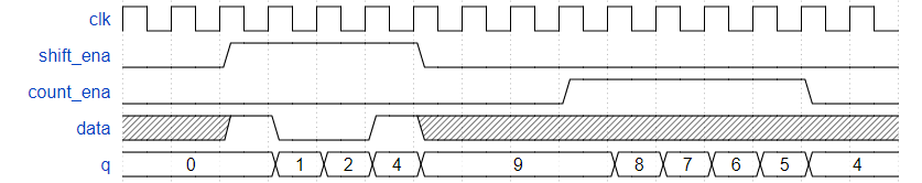
Build a four-bit shift register that also acts as a down counter. Data is shifted in most-significant-bit first when shift_ena is 1. The number currently in the shift register is decremented when count_ena is 1. Since the full system doesn’t ever use shift_ena and count_ena together, it does not matter what your circuit does if both control inputs are 1 (This mainly means that it doesn’t matter which case gets higher priority).
always @(posedge clk) begin if (shift_ena) begin q <= {q[2:0], data}; end elsebegin q <= q; end if (count_ena) begin if (q == 0) begin q <= 4'd15; end elsebegin q <= q - 1'b1; end end end endmodule
Debug
开始还有一点问题,就是data延迟了一个周期再输入,其实不用,本来就会有一个周期的延迟。
Exams/review2015 fsmseq
Question
This is the second component in a series of five exercises that builds a complex counter out of several smaller circuits. See the final exercise for the overall design.
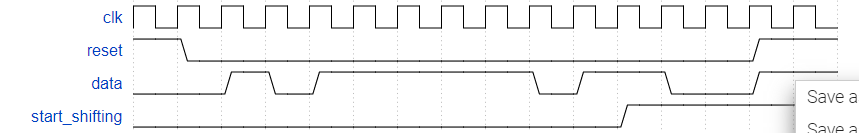
Build a finite-state machine that searches for the sequence 1101 in an input bit stream. When the sequence is found, it should set start_shifting to 1, forever, until reset. Getting stuck in the final state is intended to model going to other states in a bigger FSM that is not yet implemented. We will be extending this FSM in the next few exercises.
always @(*) begin case (state) A : next_state = data ? B : A; B : next_state = data ? C : A; C : next_state = data ? C : D; D : next_state = data ? E : A; E : next_state = E; default : next_state = A; endcase end
always @(posedge clk) begin if (reset) state <= A; elsebegin state <= next_state; end end
assign start_shifting = (state == E); endmodule
Exams/review2015 fsmshift
Question
This is the third component in a series of five exercises that builds a complex counter out of several smaller circuits. See the final exercise for the overall design.
As part of the FSM for controlling the shift register, we want the ability to enable the shift register for exactly 4 clock cycles whenever the proper bit pattern is detected. We handle sequence detection in Exams/review2015_fsmseq, so this portion of the FSM only handles enabling the shift register for 4 cycles.
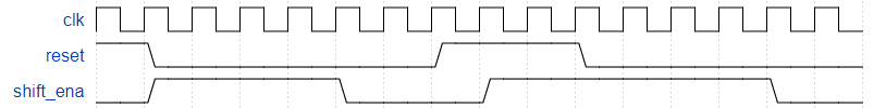
Whenever the FSM is reset, assert shift_ena for 4 cycles, then 0 forever (until reset).
module top_module ( input clk, input reset, // Synchronous reset output shift_ena); reg [2:0] cnt; always @(posedge clk) begin if (reset) cnt <= 0; elsebegin if (cnt == 4'd3) cnt <= 4'd3; else cnt <= cnt + 1'b1; end end
always @(posedge clk) begin if (reset) shift_ena <= 1'b1; elsebegin if (cnt == 4'd3) shift_ena <= 0; else shift_ena <= 1'b1; end end endmodule
Exams/review2015 fsm
Question
This is the fourth component in a series of five exercises that builds a complex counter out of several smaller circuits. See the final exercise for the overall design.
is started when a particular pattern (1101) is detected,
shifts in 4 more bits to determine the duration to delay,
waits for the counters to finish counting, and
notifies the user and waits for the user to acknowledge the timer.
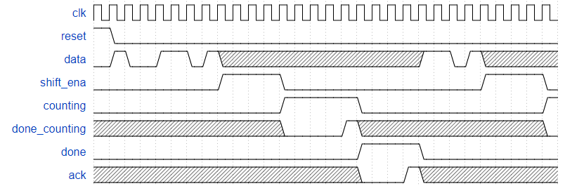
In this problem, implement just the finite-state machine that controls the timer. The data path (counters and some comparators) are not included here.
The serial data is available on the data input pin. When the pattern 1101 is received, the state machine must then assert output shift_ena for exactly 4 clock cycles.
After that, the state machine asserts its counting output to indicate it is waiting for the counters, and waits until input done_counting is high.
At that point, the state machine must assert done to notify the user the timer has timed out, and waits until input ack is 1 before being reset to look for the next occurrence of the start sequence (1101).
The state machine should reset into a state where it begins searching for the input sequence 1101.
Here is an example of the expected inputs and outputs. The ‘x’ states may be slightly confusing to read. They indicate that the FSM should not care about that particular input signal in that cycle. For example, once a 1101 pattern is detected, the FSM no longer looks at the data input until it resumes searching after everything else is done.
This is the fifth component in a series of five exercises that builds a complex counter out of several smaller circuits. You may wish to do the four previous exercises first (counter, sequence recognizer FSM, FSM delay, and combined FSM).
We want to create a timer with one input that:
is started when a particular input pattern (1101) is detected,
shifts in 4 more bits to determine the duration to delay,
waits for the counters to finish counting, and
notifies the user and waits for the user to acknowledge the timer.
The serial data is available on the data input pin. When the pattern 1101 is received, the circuit must then shift in the next 4 bits, most-significant-bit first. These 4 bits determine the duration of the timer delay. I’ll refer to this as the delay[3:0].
After that, the state machine asserts its counting output to indicate it is counting. The state machine must count for exactly (delay[3:0] + 1) * 1000 clock cycles. e.g., delay=0 means count 1000 cycles, and delay=5 means count 6000 cycles. Also output the current remaining time. This should be equal to delay for 1000 cycles, then delay-1 for 1000 cycles, and so on until it is 0 for 1000 cycles. When the circuit isn’t counting, the count[3:0] output is don’t-care (whatever value is convenient for you to implement).
At that point, the circuit must assert done to notify the user the timer has timed out, and waits until input ack is 1 before being reset to look for the next occurrence of the start sequence (1101).
The circuit should reset into a state where it begins searching for the input sequence 1101.
Here is an example of the expected inputs and outputs. The ‘x’ states may be slightly confusing to read. They indicate that the FSM should not care about that particular input signal in that cycle. For example, once the 1101 and delay[3:0] have been read, the circuit no longer looks at the data input until it resumes searching after everything else is done. In this example, the circuit counts for 2000 clock cycles because the delay[3:0] value was 4’b0001. The last few cycles starts another count with delay[3:0] = 4’b1110, which will count for 15000 cycles.
It’s ok to have all the code in a single module if the components are in their own always blocks, as long as it’s clear which blob of code corresponds to which hardware block. Don’t merge multiple always blocks together, as that’s hard to read and error-prone.
always @(posedge clk) begin if (reset) begin delay <= 0; end elsebegin if (shift_ena) begin integer i; delay[0] <= data; for (i = 0; i < 3; i = i + 1) begin : loop delay[i + 1] <= delay[i]; end end end end
always @(posedge clk) begin if (reset) begin k_cnt <= 0; end elsebegin if (counting) begin if (k_cnt == 10'd999) begin k_cnt <= 0; end elsebegin k_cnt <= k_cnt + 1'b1; end end end end
always @(posedge clk) begin if (reset) begin d_cnt <= 0; end elsebegin if (state == B3) begin d_cnt <= {delay[2:0], data}; end elseif (k_cnt == 10'd999) begin d_cnt <= d_cnt - 1'b1; end end end
always @(posedge clk) begin if (reset) begin done_counting <= 0; end elsebegin if ((k_cnt == 10'd998) & (d_cnt == 0)) begin done_counting <= 1'b1; end elsebegin done_counting <= 0; end end end assign count = d_cnt; endmodule
Debug
开始边界条件写错了,k_cnt == 10'd998 多写了一个数。
Exams/review2015 fsmonehot
Question
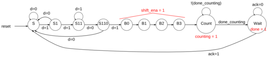
Given the following state machine with 3 inputs, 3 outputs, and 10 states:
Derive next-state logic equations and output logic equations by inspection assuming the following one-hot encoding is used: (S, S1, S11, S110, B0, B1, B2, B3, Count, Wait) = (10’b0000000001, 10’b0000000010, 10’b0000000100, … , 10’b1000000000)
Derive state transition and output logic equations by inspection assuming a one-hot encoding. Implement only the state transition logic and output logic (the combinational logic portion) for this state machine. (The testbench will test with non-one hot inputs to make sure you’re not trying to do something more complicated. See fsm3onehot for a description of what is meant by deriving logic equations “by inspection” for one-hot state machines.)
Write code that generates the following equations:
B3_next – next-state logic for state B3
S_next
S1_next
Count_next
Wait_next
done – output logic
counting
shift_ena
Logic equations for one-hot state transition logic can be derived by looking at in-edges of the state transition diagram.